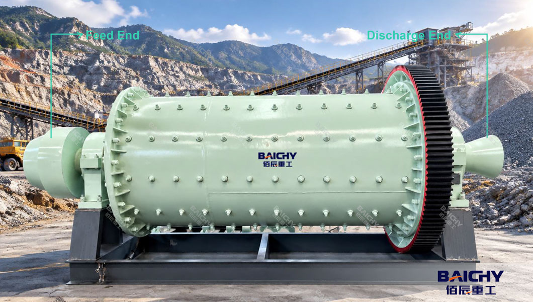
A ball mill is one of the most widely used pieces of equipment for grinding materials into fine powder. You will find it in mining, cement production, ceramics, and chemical processing. Although the basic idea is simple—a rotating drum filled with steel balls—the actual structure of a ball mill is carefully engineered. Each component has a specific job, and together they ensure the machine runs efficiently and reliably. This article explains the main structural parts of a ball mill in plain language, helping you understand not just what each part is, but why it matters.
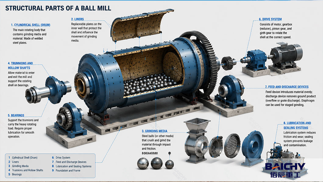
1. Cylindrical Shell (Drum)
The shell is the heart of the ball mill. It is a large hollow cylinder, usually made from thick steel plates welded together. The shell rotates around a horizontal axis and contains both the grinding media (steel balls) and the material being processed.
Inside the shell, the surface is protected by removable liners. Without liners, the grinding balls would quickly wear through the steel shell. The length-to-diameter ratio of the shell varies depending on the application. Some mills are short and used for coarse grinding, while longer shells are common in fine grinding and cement milling.
2. Liners
Liners are replaceable plates fixed to the inner wall of the shell. Their main job is to protect the shell from impact and abrasion. At the same time, the shape and profile of the liners affect how the grinding balls move inside the drum.
Common liner materials include:
- High-manganese steel – good for heavy impact and coarse grinding
- High-chromium steel – excellent abrasion resistance
- Rubber– quieter operation and suitable for less abrasive materials
- Ceramic – used when metal contamination must be avoided, such as in the pharmaceutical or ceramic industries
Choosing the right liner extends the life of the mill and improves grinding performance.
3. Grinding Media
The grinding media are the balls themselves. They do the actual work of breaking down the material through impact and friction as the drum rotates. Steel balls are the most common choice, but ceramic balls, stainless steel balls, and even natural stone pebbles can be used depending on the material and the risk of contamination.
Media size matters. Larger balls deliver stronger impact for coarse crushing, while smaller balls are better for fine grinding. In many mills, different ball sizes are mixed to balance impact and attrition.
4. Trunnions and Hollow Shafts
At each end of the shell, there are short cylindrical extensions called trunnions (or hollow shafts). These serve two purposes:
1. They provide a passage for material to enter and exit the mill.
2. They rest on the bearings and support the rotating drum.
The feed-end trunnion allows raw material to enter the shell, while the discharge-end trunnion lets the ground product leave. In some designs, the discharge end uses a grate or diaphragm to control the size of particles leaving the mill.
5. Bearings
Bearings support the heavy rotating mass of the drum through the trunnions. Depending on the mill size, these can be:
- Trunnion (journal) bearings – common in larger mills, often with hydrostatic or hydrodynamic lubrication
- Slide shoe bearings – used in some modern designs, offering simpler foundation requirements
- Roller bearings – found in smaller mills
Because the rotating assembly can weigh tens or even hundreds of tons, the bearings must be robust and properly lubricated. Good lubrication reduces friction, dissipates heat, and prevents premature wear.
6. Drive System
The drive system rotates the shell at the correct speed. A typical setup includes:
- An electric motor
- A gearbox or reducer to lower the speed and increase torque
- A pinion gear meshing with a large girth gear (ring gear) attached to the shell
Some smaller mills use a direct coupling or belt drive. The speed is important—running too slow means the balls will not lift properly, while running too fast can cause the balls to stick to the wall due to centrifugal force. Most ball mills operate at 65%–85% of their critical speed.
7. Feed and Discharge Devices
The feed device introduces raw material into the mill evenly. It usually includes a hopper, a feeder (such as a screw or vibrating feeder), and an inlet chute leading to the feed trunnion.
The discharge device removes the ground product. There are two main designs:
- Overflow discharge – material flows out when it reaches the level of the discharge opening; suitable for fine grinding
- Grate discharge – a perforated plate retains large balls and coarse particles while allowing fine material to pass; better for coarse grinding and higher throughput
Some mills also include a diaphragm (partition plate) that divides the shell into two or more compartments, each with different ball sizes for staged grinding.
8. Lubrication and Sealing Systems
The lubrication system supplies oil or grease to the bearings and drive components. Large mills often use a combination of high-pressure and low-pressure oil pumps. High-pressure oil lifts the trunnion slightly during startup to reduce friction, while low-pressure oil maintains a lubricating film during operation.
Seals around the trunnions prevent slurry or powder from leaking out and stop external contaminants from entering. Common sealing types include labyrinth seals, packing seals, and mechanical seals.
9. Foundation and Frame
The foundation absorbs vibration and supports the full weight of the rotating assembly. It is usually a reinforced concrete slab designed according to the mill's dimensions and operating loads. A stable, level foundation is essential—misalignment can cause uneven wear on liners and bearings, and may even lead to mechanical failure.
A ball mill may look like a simple rotating drum, but its structure is the result of careful engineering. The shell, liners, grinding media, trunnions, bearings, drive system, feed/discharge devices, lubrication system, and foundation all work together to achieve efficient, reliable grinding. Understanding these components helps operators, maintenance teams, and purchasing managers make better decisions about selection, operation, and upkeep—ultimately extending the service life of the equipment and improving plant productivity.




 2026-09-28





 86-15093113821
 86-15093113821