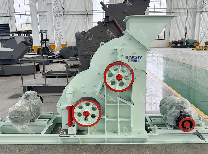
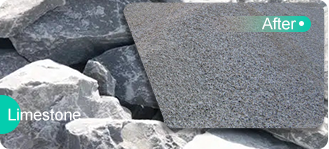
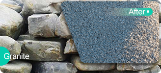
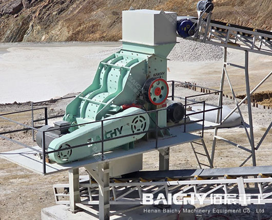
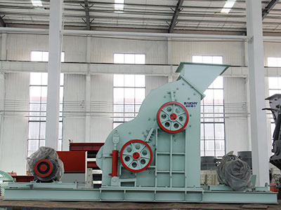
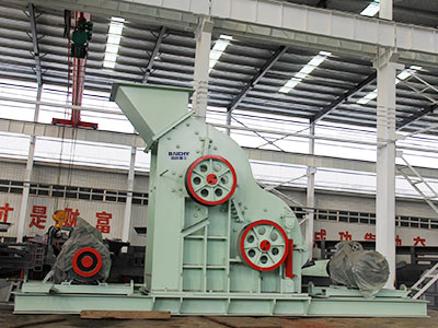
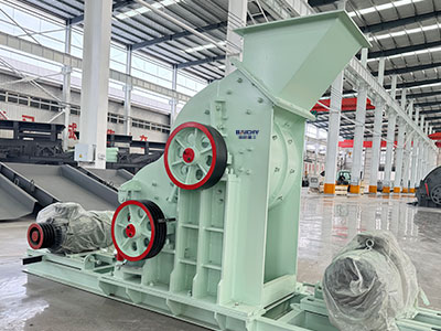
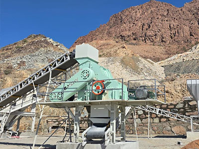
A double rotor hammer crusher is an advanced crushing machine for size reduction of soft-to-medium-hard materials. It features two parallel rotors—each equipped with high-strength hammer heads—working in tandem to deliver superior crushing performance.


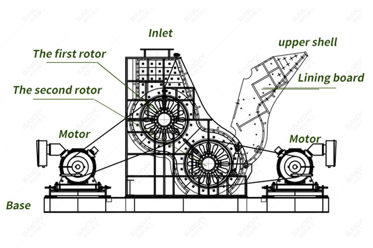
Rotor: The rotor is the core component of the crusher. It consists of a shaft and hammers. The hammers are usually made of high - strength alloy steel to withstand the impact forces during the crushing process.
Crushing ChambersThere are two distinct crushing chambers in a two - stage hammer crusher. The first - stage chamber is designed to handle larger feed sizes and break the materials into intermediate - sized particles. The second - stage chamber is focused on further reducing the particle size and achieving a more refined product. The chambers are usually lined with wear - resistant materials such as manganese steel to protect the crusher body from abrasion caused by the materials.
Feed Hopper and Discharge Outlet: The feed hopper is located at the top of the crusher and is used to receive and guide the materials into the first - stage crushing chamber. The discharge outlet is at the bottom of the second - stage crushing chamber and is designed to allow the crushed materials to be discharged smoothly.
High Reduction Ratio: Achieves single-pass size reduction from large feed to fine output (<3mm) through dual crushing stages.
Clog Resistance: Grate-free designs prevent blockages when processing wet or sticky materials such as clay-rich limestone or wet coal.
Energy and Space Efficiency: Combines primary and secondary crushing in one unit, reducing power consumption and eliminating additional conveyors.


The operation of a double rotor hammer crusher relies on impact, shearing, and grinding. It destroys rock using high-speed kinetic energy. The process occurs in three distinct stages:
Stage 1: The First Rotor
Material is fed into the machine from the top. It immediately encounters the first high-speed rotor. The hammers attached to this rotor strike the material with massive force, breaking large rocks into medium-sized chunks.
Stage 2: The Second Rotor
The crushed material from the first rotor is thrown directly into the path of the second rotor (which often rotates at a higher speed). Here, the material is pulverized further into fine particles.
Stage 3: Mutual Crushing and Discharge
A unique feature of this design is that materials are not just hit by hammers; they also collide with other flying rocks and the inner liners of the machine. Finally, the crushed material falls through the discharge opening at the bottom.


| Model | Feeding size(mm) | Output Size (mm) | Capacity (t/h) | Motor Power (kw) | Overall Dimension (mm) |
| 2PC600X400 | <100 |
<3mm
(0.5~0.075mm 50%
0.6~2mm 35%
2~3mm 15%) |
15-25 | 2x22 | 2350×926×1630 |
| 2PC800X600 | <100 | 45-60 | 2x55 | 3300×1250×1730 | |
| 2PC1000X800 | <120 | 50-70 | 2x90 | 5650×2067×2766 | |
| 2PC1000X1200 | <130 | 80-100 | 2x110 | 5650×2419×2765 | |
| 2PC1200X1400 | <150 | 100-120 | 2x160 | 5900×2660×2790 | |
| 2PC1400X1600 | <180 | 120-180 | 2x250 | 6000×2880×4600 | |
| 2PC1600X2000 | <200 | 200-250 | 2x400 | 7400×3500×4266 |
*The output will vary according to different materials, feed particle size and other factors
Save Time! Get A Detailed Quotation Quickly.